INFINITY OWNER’S MANUAL (To Be Retained by Owner After Installation by Authorized Savaria Concord Dealer) The Infinity Residential Elevator must be installed, maintained and ser viced by an authorized SAVARIA CONCORD DEALER only! Under no circumstances is anyone other than a trained and authorized Savaria Concord Dealer to install, adjust, service or modify any mechanical or electrical device on this lift. Failure to follow this warning can result in safety systems being compromised or defeated, which can result in serious injury or death. Savaria Concord Lifts Inc. accepts no liability for property damage, warranty claims or personal injury, including death, in this circumstance. Lift and elevator passenger safety is the result of countless details in the equipment’s design, manufacture and installation. After installation, reliable operation and continued assurance of safe operation requires regular service and inspection to be carried out at least twice per year, or more frequently where usage or environment dictates or as required by local jurisdiction. The owner is responsible to ensure that regular service and inspections occur in a timely manner. The owner must refer to this manual for operating instructions and precautions for usage of this Infi nity Residential Elevator. On completion of installation, the dealer must provide the owner with the information below and ensure it is recorded in the owner’s manual. Any ser vice and /or maintenance must also be recorded in the Maintenance Record section of this manual by the authorized Savaria Concord dealer or the owner. Your Savaria Concord Dealer will provide a copy of the manufacturer’s limited parts warranty and documentation relating to any labour warranty offered by your Dealer. FOR OWNER’S RECORDS INFINITY RESIDENTIAL ELEVATOR OWNER’S MANUAL 1. GENERAL SPECIFICATIONS 2. STANDARD FEATURES 3. OPTIONAL FEATURES OPERATING THE ELEVATOR FROM THE LANDING CONTROLS Automatic Operation Constant Pressure Operation OPERATING THE ELEVATOR FROM THE CAB CONTROLS Automatic Operation Constant Pressure POWER FAILURE AND EMERGENCY LOWERING 7. EMERGENCY MACHINE ROOM MANUAL LOWERING DEVICE EMERGENCY HANDS - FREE PHONE (Optional) MAINTENANCE AND INSPECTION CHECKS 11. MAINTENANCE 1. GENERAL SPECIFICATIONS INFINITY LUXURY RESIDENTIAL ELEVATOR
Verify requirements prior to installation of power supply.
Constant Pressure or Automatic Push Button
Plywood (standard) or Hardwood (optional)
Stainless Steel (standard) or Brass (optional)
Stainless Steel (standard) or Brass (optional)
Solid Melamine Panels (standard) or Raised Woods or
“Car in Use” Illuminated Hall Buttons
Emergency Battery Powered Lowering & Lighting with
Solid Ceiling with Four Stainless Steel Pot Lights
Vertical Keyed Stainless Steel Control Panel
INFINITY STANDARD RESIDENTIAL ELEVATOR
Verify requirements prior to installation of power supply.
“Car in Use” Illuminated Hall Buttons
Emergency Battery Powered Lowering & Lighting with
Solid Ceiling with Four Stainless Steel Pot Lights
Vertical Keyed Stainless Steel Control Panel
2. STANDARD FEATURES Cab Key Switch (Figure 1-A)
The key switch turns the cab controls ON and OFF. It is provided to limit the use of the elevator to authorized persons only. Cab Operating Panel Buttons (Figure 1-B) Automatic Control
The Automatic Control Panel buttons facilitate the UP/DOWN movement of the cab between landings. Once the selected landing button is pressed,
the cab will automatically move to the landing. The cab will stop when the selected landing is reached. Constant Pressure Control
buttons facilitate the UP/DOWN movement of the cab between landings. The selected landing button must be pressed and held until the cab moves to the landing. The cab will stop when the button is released or when the selected
Figure 1 3 Stop COP Panel Door Open Button (Figure 1-C)
The elevator door/gate will close automatically after a pre-set
adjustable time of 8 seconds. This button can be pressed to open
the door/gate when the cab is at a landing. Emergency Stop Button (Figure 1-E)
The button can be set to Stop at any time to stop the cab and activate the alarm buzzer.
The button can be pressed at any time to sound the alarm in case of an emergency. If equipped with the Hands-Free Telephone, hold down the button for approximately 3 to 10 seconds to activate the telephone line. Refer to section 9 for more details. 6) Handrail
A single handrail is mounted on the Cab Operating Panel side of the cab. 7) Emergency
The COP emergency light remains ON in the event of a main power failure. The emergency light uses a Battery Back-Up system with an automatic recharger. Landing Hall Call Station Controls
Hall Call Stations are installed at all landings to move the cab to the landing from which it
Figure 2 Hall Call Station
is being called. An optional key switch limits the elevator’s use to authorized persons only. Landing Door and/or Gate Interlock
The Landing Door/Gate lock prevents the movement of the cab unless the door/gate is in the closed and locked position. If the door/gate is not completely closed, the cab will not move. Emergency Battery Operation
In the event of a building power failure, the door/gate system is provided with an temporary power back up system to continue the opening operation for a number of times. On resuming normal building power, the back up system will turn OFF and begin automatic recharging.
3. OPTIONAL FEATURES Automatic Door Opener
Press the Landing Hall Call button to call the elevator. The
entrance door will open automatically once the elevator stops
Press the Remote Control (if equipped) to open the entrance
door once the elevator stops at the landing.
Push ’n’ Go allows the entrance door to open automatically
with a slight push to the door itself. The door timer is
inoperative when this feature is activated. Automatic Gate Opener
Press the Landing Hall Call button to call the elevator. The
Gate will open automatically once the elevator stops at the
landing and the entrance door is fully open.
Manually open the entrance door, the Gate will open
automatically once the entrance door is fully open.
If the cab is equipped with a gate, the gate must be closed after exiting the cab. If the gate is left open, all controls will
An “entry” and “exit” timer allows approximately nine seconds before the hall buttons become operational. This
delay allows time for a person to enter/exit the cab. OPERATING THE ELEVATOR FROM THE LANDING CONTROLS Automatic Operation
Insert the key (if equipped) into the switch on the Hall Call
and turn the key to the ON position.
Press the Hall Call button once and release. The elevator
will automatically come to your landing.
Turn the key (if equipped) to the OFF position and remove
If required, turn the door handle and pull the door open.
If the cab is equipped with a manual gate, slide the gate
Once inside the cab, close the gate, insert the key (if
equipped) into the key switch, and turn the key to the ON
When using the landing controls, the cab can only be moved
(called) to the level from which you are calling. When using
the control buttons in the cab, the cab can be moved to any
WHEELCHAIR WHEELS MUST BE LOCKED AT ALL TIMES WHEN THE ELEVATOR IS MOVING Constant Pressure Operation
Insert the key (if equipped) into the switch on the Hall Call
and turn the key to the ON position.
Press and maintain constant pressure on the Hall Call
button until the cab stops at your landing. To stop the cab at
any point simply release the Hall Call button.
Turn the key (if equipped) to the OFF position and remove
If required, turn the door handle and pull the door open.
If the cab is equipped with a manual gate, slide the gate
open and enter the cab. Once inside the cab, close the gate,
insert the key (if equipped) into the key switch, and turn the
OPERATING THE ELEVATOR FROM THE CAB CONTROLS Automatic Operation
Insert the key (if equipped) into the switch located in the Cab
Operating Panel. Turn the key to the ON position.
Press the selected Landing button once and release. The
elevator will automatically travel to and stop at the selected
Turn the key (if equipped) to the OFF position and remove the
Unlock the wheelchair wheels and exit the cab (if applicable). Constant Pressure
Insert the key (if equipped) into the switch located in the Cab
Operating Panel. Turn the key to the ON position.
Press and maintain constant pressure on the selected Landing
button to move the elevator. Maintain constant pressure until
the elevator automatically stops at the desired landing. To stop
the elevator at any point simply release the Hall Call button.
Release the Landing button when the elevator arrives at the
Turn the key (if equipped) to the OFF position and remove the
Unlock the wheelchair wheels and exit the cab (if applicable).
If the cab is equipped with a gate, the gate must be closed after exiting the cab. If the gate is left open, all controls will
An “entry” and “exit” timer allows approximately nine seconds before the hall buttons become operational. This
delay allows time for a person to enter/exit the cab. POWER FAILURE AND EMERGENCY LOWERING
In the event of a power failure, the elevator is equipped with a
Battery Back-Up system that allows the user to lower the elevator
from inside of the cab itself. This device operates on batteries
and is only activated if a main power supply failure occurs. The
For elevators with automatic operation, press any
Landing button below the fl oor where the elevator is
For elevators with constant pressure operation,
press any Landing button below the fl oor where the
elevator is located and maintain constant pressure
until the cab is level with the lower landing.
On arrival at the selected fl oor, the landing door will
If the door is equipped with an automatic gate, the gate will
Release the button, remove the key, open the manual gate
7. EMERGENCY
In the event of a main power failure, the emergency cab light will
MACHINE ROOM MANUAL LOWERING DEVICE
In the event of power failure, the cab can be moved to a lower
level from the Machine Room by using the following procedures:
Obtain the key to unlock the door to the Machine Room
where the elevator pump unit is located (if applicable).
Instruct the person(s) in the elevator to remain calm and
Manual Lowering Knob (pull to lower lift) Figure 3 EPV Valve
the owner’s key to unlock the Controller Tank cover. The
Locate the red manual release knob on the EPV Valve and
pull the knob to lower the cab. Refer to Figure 3. Maintain
a constant pull on the knob until the elevator reaches the
lowest landing and stops automatically. (Although you may
not be able to see the elevator this is readily detected.
There will be no further noise as the oil fl ows to the
To exit the cab, open the lower landing door and assist the
After passenger(s) have exited the cab, remove the cab
key. Make sure the landing door is closed, reconnect the
disconnect switch in the machine room and lock the door. EMERGENCY HANDS - FREE PHONE (Optional)
If your lift is equipped with an Emergency Hands-Free
Telephone, press and hold down the Alarm button for 3 to
10 seconds to activate the phone line. A 3 to 10 second time
delay (adjustable by the installing technician) will occur.
Alarm button once the call is picked up by the
The system will automatically dial out to a pre-programmed
telephone number as set up by the installing technician. MAINTENANCE AND INSPECTION CHECKS
Regular maintenance will keep the Infi nity in proper operating
condition. Please remember, as the owner of this elevator, you
are responsible for making sure that maintenance and upkeep are
done on a regularly scheduled basis. To ensure proper operating
condition of your unit, the items listed below must be inspected
and, if necessary, serviced every six (6) months. Additional
inspections may be required depending on usage.
Tighten all rail and cab fastening bolts.
Lubricate the door hinges and adjust the door closure if
Lubricate the rails with light grease, such as white lithium.
Inspect the travelling cable for wear. Replace if any cuts or
Check for any hose/pipe leaks. Replace and/or tighten the
fi ttings to correct any hydraulic leaks found.
Check the fl uid level of the pump reservoir (with the elevator
at its lowest landing), and fi ll as required. (Use Grade 32
Hydraulic Oil). There must be at least 1” inch of oil on the
Tighten any hose connections or bleeder valves found
loose. Check the hydraulic cylinder (jack) for any leaks. If
necessary, the packing seals may have to be replaced.
Replace the batteries inside the control panel as indicated
To perform the required maintenance to the Kwiklock (if
equipped), call your Authorized Savaria Concord Dealer. UNDER NO CIRCUMSTANCES SHOULD THE PUMP CONTROLS OR VALVE SETTINGS BE ADJUSTED EXCEPT BY AN AUTHORIZED SAVARIA CONCORD DEALER 11. MAINTENANCE
It is recommended that the Owner update the Maintenance Record after eachservice call. Reason for Call Comments
Infi nityResidential ElevatorOwner’s Manual
Savaria Concord Lifts, Inc. www.savariaconcord.com
Sales107 Alfred Kuehne Blvd. Brampton, Ontario, L6T 4K3 CanadaTel: (905) 791-5555 Fax: (905) 791-2222Toll Free: 1-800-661-5112
JULY 15, 2007 ETAP TIP – No. 005 Project View (Part 4 - Libraries) Applicable ETAP Versions: 5.5.0, 5.5.5, 5.5.6 (For lower versions, some of the descriptions and procedures below may differ in some ways) This is a continuation of ETAP TIP No. 002, 003, & 004. As usual, you may run Etap program and open the “Example-ANSI.oti” project located at C:\ETAP 55X \Example-ANSI
McDonald's USA Ingredients Listing for Popular Menu Items Provided below is a listing of components in our popular menu items by category, followed by the ingredient statements for those components. Allergens containedwithin these components are indicated in capital type at the end of each respective ingredient statement. We encourage customers to check these statementsregularly as ingredie
 INFINITY
 INFINITY RESIDENTIAL
 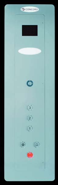 2. STANDARD
 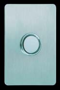 The button can be pressed at any time to sound the alarm in case of an emergency. If equipped with the Hands-Free Telephone, hold down the button for approximately 3 to 10 seconds to activate the telephone line. Refer to section 9 for more details.
 OPERATING THE ELEVATOR FROM THE LANDING
 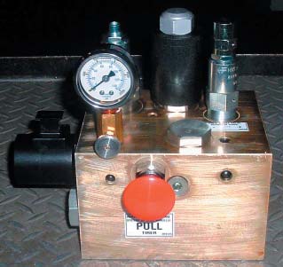 7. EMERGENCY
  MAINTENANCE AND INSPECTION CHECKS
 Infi nityResidential ElevatorOwner’s Manual
Savaria Concord Lifts, Inc.
Infi nityResidential ElevatorOwner’s Manual
Savaria Concord Lifts, Inc.