EURAX I210, U210 Transducer for AC current or AC voltage Application
The transducer EURAX I 210 (Fig. 1) converts a sinusoidal or a distorted AC current, the EURAX U 210 converts a sinusoidal or a distorted AC voltage signal into an output signal that can serves several receiving instruments such as indicators, recorders, alarm units etc. The units are suitable for processing distorted values when using thyristors and other rectifier devices.
Available with linear or square output characteristic. Features / Benefits
● Measuring input: Sine or distorted wave-forms of AC current or sine or
distorted wave-forms of AC voltage, RMS value measurement
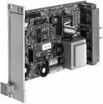
Fig. 1. Transducer for AC current or AC voltage EURAX I210/U210, front plate width 7 TE.
● Measuring output: DC current signal (load-independent or DC voltage
● Measuring principle: Logarithmic system
● The device fulfils the protection requirements of the EMC guidelines
(89/336/EWG) / The device bears the CE symbol for EMC. See “Table 1:Electromagnetic compatibility”
● Mechanical design of the transducer: Plug-in module 7 TE (35.2 mm)
or 11 TE (55.6 mm) for 19″ rack-mounted case
Layout and mode of operation
The input stage provides electric isolation and signal adaptation toinstrument level. The transducers I 210 and U 210 differ electrically
The transducer consists of an input stage ES with the converter W,
only in the input stage. The computing block consists of a preci-
a computing block RB which calculates the rms value, an output
sion rectifier, a squarer/divider and a low-pass filter. It operates with
amplifier AV, a power pack SP and a mains supply transformer Tr
logarithmic amplifiers and calculates the rms current or voltage ac-
The output amplifier is unipolar. It can supply a voltage or currentas output variable, and allows both positive (live zero) and negative
shift (suppressed zero measurement). All standard signals for ana-
log data transmission can therefore be achieved.
For AC supplies a transformer is used. For DC supplies a DC/ACinverter (DCS) is used instead of the transformer. Fig. 2. Block diagram for a function unit.
All inputs and outputs are protected against voltage surges. EURAX I210, U210 Transducer for AC current or AC voltage Technical data
AC current or AC voltageSine or distorted wave-forms
Output characteristic Input signal E
30.40.70.1000 Hz
Nominal input current IN(measuring range endvalue):
Fig. 4. Characteristic A “StandardE3 adjustable by max. ± 30%
110, 116.66, 120, 125, 133.33, 150,250, 400 or 500 V
“Standard, variable sensitivity andE3 adjustable by max. ± 30%Output signal A “Current resp. voltage magnifierE2.E3 main measuring rangemagnifiedAccuracy (acc. to DIN/IEC 688-1)
1 to 4 see “Table 3: Special features”Reference conditions Power supply
± 15%, 42 to 70 Hzpower consumption approx. 4 VA
Installation data Influence effects (maxima) included in basic error
Front plate width 7 TE (35.2 mm), AC supply
The transducer is designed for crest factors from 1 to 2.5. With
higher crest factors the instrument measures correctly only if the
peak value of the input signal does not exceed 2.5 times M . Here
it must be borne in mind that M may be exceeded by 20% (safety
factor 120%). That means with the measuring range 0.100 V
for example the peak input signal must not exceed
2.5 ×100× 1.2 = 300 V. Consequently with crest factors > 2.5 the
transducer can no longer be utilized to the full. The diagram below
shows the M range and the additional error versus the crest factor
By coding pins, removed/not re-moved, see Section “Electrical con-
Regulations
between electrically isolated circuits.
(Restriction: Version with test sock-ets for field indicator, output to front
This limitation is without significance in most cases, however, be-
cause the peak value diminishes anyhow with increasing distortionof the input signal (e.g. gating control). Environmental conditions Additional error
5 see “Table 3: Special features”EURAX I210, U210 Transducer for AC current or AC voltage Table 1: Electromagnetic compatibility
The basic standards EN 50 081-2 and EN 50 082-2 were taken in account
Conducted interference from the instrument
80 MHz … 1000 MHz: 10 V/m, 80% AM 1 kHz(Frequencies ITU, 3 V/m)
± 2 kV, 5/50 ns, 5 kHz, > 2 min.
The limits given in the standards mentioned are observed. During the interference test, occasional impairment of operating behaviour was permitted. The device fulfils the protection requirements of the EMC guidelines (89/336/EWG). The device bears the CE symbol for EMC. Table 2: Specification and ordering information
Order Code 581 – 1. Mechanical design
2) Plug-in module for 19″ rack-mounted case
2. Type / Measuring mode 3. Frequency range
1) 30.40 – 70.1000 Hz
Frequency influence: < 0.3% (16 … 25 Hz)
4. Measuring range (measuring input E) 1 , 2 and 4
Lines 1 to 7: Measuring range for characteristics A, Fig. 3, 4, 5 and 6and characteristic E, Fig. 8
Lines 8 and 9: Measuring range for characteristic B, Fig. 7Specify range (E2.E3) e.g. 90.120 V
Selection Feature 4 “Measuring range” and Feature 5 “Output signal”as well as Feature 6 “Output characteristic” to be determined together. In Section “Output characteristic” conditions laid down in Fig. 2 to 8should be noted
1 , 2 and 4 see “Table 3: Special features”
Order Code 581 – 4. Measuring range (measuring input E) 1 , 2 and 4 (continuation)
Lines A to Y: Measuring range for characteristics A, Fig. 3, 4, 5 and 6and characteristic E, Fig. 8
Line Z: Measuring range for characteristic B, Fig. 7Specify range (E2.E3) e.g. 90.120 V
Selection Feature 4 “Measuring range” and Feature 5 “Output signal”as well as Feature 6 “Output characteristic” to be determined together. In Section “Output characteristic” conditions laid down in Fig. 2 to 8should be noted
5. Output signal (measuring output A)
0.> 1.00 to 0.< 201.5 to < (4.20)
Lines 1, 9, A to D and Z: Output signals for characteristics A,Fig. 3 and 4, characteristic B, Fig. 7 and characteristic E, Fig. 8
Lines 2, 9, E and Z: Output signals for characteristics A, Fig. 5 and 6
1 , 2 and 4 see “Table 3: Special features”EURAX I210, U210 Transducer for AC current or AC voltage
Order Code 581 – 6. Output characteristic
“Standard and variable sensitivity”, see Fig. 4.
Note Feature 11 “Measuring range adjustable”
“Standard and live zero”, see Fig. 5.
Note Feature 5 “Output signal”, lines 2, 9, E or Z
“Standard, variable sensitivity and live zero”, see Fig. 6
Note Feature 11 “Measuring range adjustable” and 5 “Output signal”, lines 2, 9, E or Z
“Current resp. voltage magnifier in end range”, see Fig. 7
Note Feature 4 “Measuring range”, lines 8, 9 or Z
7. Power supply 8. Special features
Without special feature (line 0): Order code complete.
With special feature (line 1): The features to be omitted must bemarked hereafter with / (slant line) in the order code until reachingthe required feature
9. Two measuring ranges (for measuring input E) 1 and 2
1st measuring range ≥ 40 VAdditional error < ± 0.2%
1 and 2 see “Table 3: Special features”
Order Code 581 – 10. Time response 3
A) Response time < 350 ms instead of < 700 ms
residual ripple < 2% p.p. instead of < 0.5% p.p. 11. Measuring range adjustable 4 12. Improved climatic rating 5 13. Mounting parts 14. Test sockets for field indicator 6
Test voltage: Sockets versus front plate 2 kV
* Lines with letter(s) under “no-go” cannot be combined with preceding lines having the same letter under “SCODE”.
3 to 6 see “Table 3: Special features”Input measuring range (continuation)
In each case the required range terminal is selected byconnection to the appropriate input (see Section “Electri-cal connections”)
Table 3: Special features Input measuring range Time response
Response time < 350 ms instead of < 700 ms
(Both current measuring ranges use the same input,
Residual ripple < 2% p.p. instead of < 0.5% p.p.
changeover is effected with a jumper on the PCB). Measuring range adjustable Improved climatic rating Test sockets for field indicator
Test voltage: Sockets versus front plate 2 kV
(voltage drop over milliammeter ≤ 300 mV)
EURAX I210, U210 Transducer for AC current or AC voltage Electrical connections Dimensional drawings Fig. 9. EURAX plug-in module, front plate width 7 TE. Fig. 10. EURAX plug-in module, front plate width 11 TE with DC power supply.
Printed in Switzerland • Subject to change without notice • Edition 11.96 • Data sheet No. 59-I210/U210 Le
Aargauerstrasse 7CH-5610 Wohlen/SwitzerlandPhone +41 56 618 21 11Fax +41 56 618 24 58
CLINICAL GASTROENTEROLOGY AND HEPATOLOGY 2004;2:656 – 664Effectiveness of Proton Pump Inhibitors in Nonerosive RefluxBONNIE B. DEAN,* ANACLETO D. GANO, JR.,* KEVIN KNIGHT,* JOSHUA J. OFMAN,*,‡ andRONNIE FASS§*Cerner Health Insights, Beverly Hills, California; ‡Cedars-Sinai Medical Center, Department of Medicine, Los Angeles, California;and §Southern Arizona VA Health Care System, Tucson
Cutting: Self Injury and How to Help Copyright, Kaya Oakes, Original location Millions of women cut or injure themselves — here’s how to understand why they do it and how to help. My college roommate, a beautiful and intelligent young woman, always wore long-sleeved shirts — even on the hottest days of the summer. When I asked her why, she shrugged and rolled up her sleeves. Her ar
 EURAX I210, U210